
Every new hydraulic system, every hydraulic system after maintenance, and every hydraulic system after component replacement contains contamination. Weld slag from fabricated pipework, pipe scale from carbon steel tubing, machining swarf from component manufacture, assembly debris, and atmospheric dust introduced during installation — all of these enter a hydraulic system before the first drop of operating fluid is pumped. If this contamination is not removed before commissioning, it circulates through servo valves, pumps, actuators, and motors, causing accelerated wear, valve spool sticking, and premature component failure.
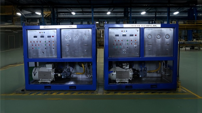
Hydraulic flushing — using a dedicated high-flow flushing rig to circulate oil through the system at high velocity, creating turbulent flow that dislodges and carries contamination to the filter elements — is the standard pre-commissioning and post-maintenance procedure for all precision hydraulic systems in aerospace, defence, and industrial applications.
Why High-Velocity Turbulent Flow Is the Key to Effective Flushing
Hydraulic contamination is not just suspended in the oil — much of it adheres to pipe walls and fittings, particularly in dead legs and low-velocity zones. Static or laminar flow conditions pass oil over this debris without disturbing it. The physics of turbulent flow — characterised by a Reynolds number above approximately 4,000 — creates velocity fluctuations and eddies that physically dislodge adhered particles from surfaces and carry them into the bulk fluid where they can be captured by the filter.
A mobile flushing rig achieves turbulent flow by delivering high flow rates relative to the pipe diameter. For a given pipe size, flow velocity needs to exceed the laminar-to-turbulent transition threshold — typically 1.5–3 m/s in hydraulic lines — which requires a flushing rig to deliver significantly higher flow than the system’s normal operating flow in many cases.
Multi-Stage Filtration Architecture
A single filter stage cannot efficiently take a heavily contaminated new system to clean servo-grade specifications in one pass. Multi-stage filtration applies progressively finer filter elements:
Stage 1 — Coarse filtration (25–100μm nominal): Removes large debris — weld slag, pipe scale, assembly contamination — without rapid clogging of fine elements.
Stage 2 — Intermediate filtration (10μm nominal): Removes medium particles that passed Stage 1.
Stage 3 — Fine filtration (3μm absolute): Final polishing to servo-grade cleanliness. Beta ratio ≥200 at 3μm ensures consistent particle removal efficiency.
Differential pressure indicators (or DP switches) on each filter stage monitor loading — when a stage approaches bypass pressure, the operator services that stage before advancing cleanliness work with the next stage.
Target Cleanliness Standards
| Application | Target Cleanliness | Standard |
|---|---|---|
| Servo valve systems | NAS 1638 Class 5–6 | NAS 1638 |
| Aircraft hydraulics | ISO 4406 14/12/9 to 16/14/11 | ISO 4406 |
| Industrial hydraulics | ISO 4406 17/15/12 or cleaner | ISO 4406 |
| General hydraulics | NAS 1638 Class 8–10 | NAS 1638 |
Applications
Aerospace: Flushing flight control system hydraulic lines, servo-valve circuits, and landing gear actuator lines before first use and after any maintenance that involved circuit opening. Typically targets ISO 4406 15/13/10 or better.
Defence: Armoured vehicle hydraulic systems, weapon system actuator circuits, and naval vessel hydraulic machinery — flushed to NAS 1638 specifications before commissioning and after major maintenance.
Industrial: New hydraulic press and machine tool installations, injection moulding machine hydraulics, and process plant hydraulic actuator circuits — flushed to achieve ISO 4406 17/15/12 or better before energising servo valves.
Rail and metro: Hydraulic braking system circuits and bogie suspension hydraulics — flushed to prevent contamination-related valve failures in service.
Marine and offshore: Ship steering gear, ballast control systems, and subsea hydraulic lines — flushed to specification before handover.
Neometrix Mobile Hydraulic Flushing Rig
A sophisticated skid-mounted system using controlled high-velocity turbulent flow, multi-stage filtration (to 3μm absolute), thermal regulation, and real-time monitoring to achieve NAS 1638 Class 6 or better (ISO 4406 16/14/11) in aerospace, defence, and industrial hydraulic circuits. Mobile, on-site deployable, with optional PLC-based HMI for automated flushing sequences and digital cleanliness records.
FAQ
Q: What is the Reynolds number and why does it determine flushing effectiveness?
A: The Reynolds number (Re = ρvD/μ) characterises whether flow is laminar (Re < 2,300) or turbulent (Re > 4,000). In laminar flow, fluid moves in parallel layers with minimal cross-stream mixing — contamination adhered to pipe walls is not disturbed. In turbulent flow, random velocity fluctuations and eddies create forces perpendicular to the flow direction that physically dislodge particles from surfaces and carry them to the filter. Achieving turbulent flow in the system being flushed is therefore the primary requirement for effective hydraulic flushing, and requires the flushing rig to deliver sufficient flow velocity for the pipe sizes involved.
Q: How do you verify a hydraulic system has been flushed to the required cleanliness?
A: Cleanliness verification is performed by taking representative oil samples from specified sampling points in the system and analysing them with a particle counter. ISO 4406 analysis counts particles in three size ranges (>4μm, >6μm, >14μm) and reports the cleanliness as a three-number code (e.g., 16/14/11). NAS 1638 analysis counts particles in five size ranges and assigns a class number. Flushing is considered complete when multiple consecutive samples from all required sampling points meet or exceed the specified cleanliness target, with stable or improving cleanliness trend confirming the system has reached equilibrium.
Q: Why is temperature regulation important during hydraulic flushing?
A: Oil viscosity drops significantly with temperature, increasing flow velocity for a given pump output (beneficial for achieving turbulent flow). However, very high temperatures risk thermally damaging seals, hoses, and system components during flushing. Most flushing specifications maintain oil temperature between 40–60°C — warm enough for good flow characteristics and effective flushing, cool enough to be safe for system components. Temperature regulation via heat exchanger and thermostat maintains this range throughout the flushing process.
Neometrix Defence Ltd. manufactures mobile hydraulic flushing rigs for aerospace, defence, and industrial hydraulic system commissioning. [email protected] | +91-7777-876-876