Valves — directional control, pressure relief, check, and proportional types — are among the most widely used components across hydraulic and pneumatic systems in every industrial, automotive, aerospace, and defence sector. Each valve type has distinct performance requirements, and a comprehensive valve test rig must be capable of verifying these across the full range of valve technologies a manufacturer or end-user organisation deals with.
A general-purpose valve test rig provides the flow, pressure, and electrical signal generation capability needed to characterise valve performance against industry standards — covering endurance, hysteresis, response time, flow accuracy, pressure drop, and leakage tests across hydraulic and pneumatic valve families.
Core Test Capabilities for Valve Performance Verification
Endurance Testing: Cycling the valve through its operating range repeatedly — tens of thousands to millions of cycles — to verify long-term durability and identify wear-related performance degradation before it would occur in service.
Hysteresis Testing: Measuring the difference in valve response (flow or position) between increasing and decreasing command signals at the same nominal command level — critical for valves used in closed-loop control applications where consistent response in both directions matters.
Impulse Testing: Subjecting the valve to rapid pressure pulses or step changes to verify structural integrity and seal performance under dynamic loading conditions rather than steady-state operation alone.
Flow Compensation and Flow Accuracy Testing: Verifying that flow-control and pressure-compensated valves maintain accurate flow output across varying upstream/downstream pressure conditions — essential for valves used in applications where load pressure varies during operation.
Response Time Testing: Measuring how quickly a valve transitions from one state to another following a command signal change — critical for safety-related valves and dynamic control applications where slow response could compromise system performance or safety.
Pressure Drop Testing: Characterising the pressure loss across the valve at various flow rates — essential data for system designers sizing valves correctly for a given hydraulic or pneumatic circuit.
Leakage Testing: Verifying internal and external leakage rates meet specification — internal leakage affects control precision and energy efficiency; external leakage is a safety and environmental concern.
Pull-In and Drop-Out Testing: For solenoid-operated valves, verifying the electrical signal threshold at which the valve activates (pull-in) and deactivates (drop-out) — important for control system design margins and reliable operation across supply voltage variation.
International Standards Referenced
| Standard | Scope |
|---|---|
| ISO 4413 | Hydraulic fluid power systems — safety rules |
| ISO 6403 | Hydraulic control valves — test methods |
| SAE J1271 | Hydraulic directional control valve test procedures |
| ANSI/FCI 70-2 | Control valve seat leakage classification |
| DIN 24312 | Directional control valves — testing (Europe) |
| ISO 4406 / NAS 1638 | Fluid cleanliness — relevant to valve test environment |
Why a General-Purpose Test Rig Matters for Multi-Product Manufacturers
Organisations that design, manufacture, or maintain multiple valve types — directional control valves, pressure relief valves, proportional valves, solenoid valves — across both hydraulic and pneumatic systems face a practical challenge: building or buying a dedicated single-purpose test rig for every valve family is capital-intensive and creates underutilised equipment.
A general-purpose valve test rig with reconfigurable fixtures, programmable test sequences, and instrumentation covering the full range of relevant test parameters (flow, pressure, position, electrical signal generation, temperature) allows one capital investment to serve testing needs across an entire valve product range — switching between test programmes via software configuration rather than hardware changes.
Applications by Industry
Industrial Hydraulics: Manufacturers and end-users of directional control, pressure relief, and proportional valves used across manufacturing, construction, and process industries.
Aerospace and Defence: Hydraulic and pneumatic valves used in aircraft systems, ground support equipment, and defence vehicle hydraulics, where documented test compliance is typically required for procurement and quality assurance.
Automotive: Solenoid valves, hydraulic control valves for transmissions and braking systems, and pneumatic valves for commercial vehicle air systems.
Railways: Pneumatic valves in braking systems and hydraulic valves in suspension and damping systems requiring endurance and reliability verification.
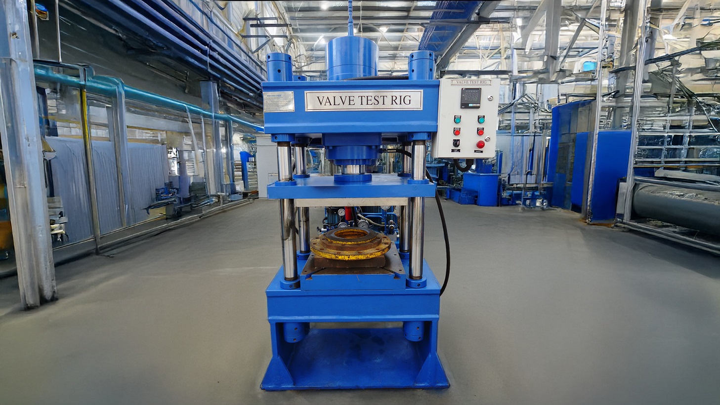
Neometrix Valve Test Rig
A versatile valve test system supporting hydraulic and pneumatic valve performance verification across endurance, hysteresis, impulse, flow compensation, flow accuracy, response time, pressure drop, leakage, and pull-in/drop-out test protocols.
→ View Full Specifications
→ Request a Quote
FAQ
Q: What is the difference between hysteresis testing and response time testing for valves?
A: Hysteresis testing measures the difference in valve output (flow or position) between increasing and decreasing command signals at the same nominal command level — it characterises consistency of response direction-independently. Response time testing measures how quickly the valve transitions from one state to another following a step change in command signal — it characterises dynamic speed of response. Both matter for closed-loop control applications: hysteresis affects positioning accuracy, while response time affects how quickly the system can react to changing conditions.
Q: What is pull-in and drop-out testing for solenoid valves?
A: Pull-in voltage (or current) is the minimum electrical signal level at which a solenoid valve activates and moves to its energised position. Drop-out voltage is the level below which the valve de-energises and returns to its rest position. These thresholds matter for control system design — engineers need margin between the supply voltage range and the pull-in/drop-out thresholds to ensure reliable valve operation across normal voltage variation, temperature effects on coil resistance, and supply degradation over the valve’s service life.
Q: Why is endurance testing run for tens of thousands or millions of cycles?
A: Many valve failure modes — wear of sealing surfaces, fatigue in springs and mechanical linkages, solenoid coil degradation — only manifest after extended cyclic use, not in short-duration testing. Running endurance tests for the number of cycles representative of the valve’s intended service life (which can be millions of cycles for some industrial and automotive applications) is the only way to verify the valve will maintain performance throughout its design life rather than degrading prematurely.
Q: Can one valve test rig handle both hydraulic and pneumatic valves?
A: A general-purpose valve test rig designed with both hydraulic and pneumatic circuits, appropriate instrumentation for both fluid types, and software-configurable test sequences can test both valve categories on one platform. This requires the rig to include both a hydraulic power unit and a pneumatic supply circuit, along with sensors and control electronics suited to both fluid power domains, but provides significant capital efficiency for organisations dealing with both valve types.
Neometrix Defence Ltd. manufactures valve test rigs for industrial, aerospace, automotive, and defence hydraulic and pneumatic valve testing. [email protected] | +91-7777-876-876