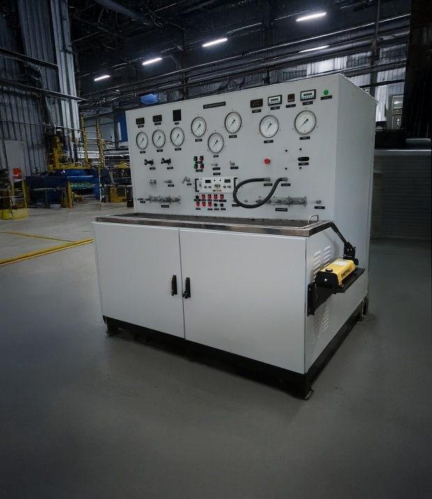

Modern aircraft and many defence vehicles depend on hydraulic systems for safety-critical functions — flight control surfaces, landing gear, weapon system actuation, braking. The consequences of total hydraulic failure in these applications are severe enough that designs incorporate redundant, independent hydraulic circuits — if one system fails, a second, completely independent system can take over the critical function. Verifying that this redundancy actually works as designed requires test equipment capable of powering, monitoring, and selectively failing two independent hydraulic circuits simultaneously.
A dual power hydraulic test rig provides two independent hydraulic power sources and control circuits within a single test platform, enabling engineers to test components and systems that rely on hydraulic redundancy — verifying not just that each circuit works individually, but that the overall system behaves correctly when one circuit is degraded or fails.
Why Dual Power Testing Matters for Redundant Systems
Many critical aircraft and defence hydraulic systems are not single circuits — they are dual or even triple redundant architectures, where:
- Each hydraulic circuit is powered, plumbed, and controlled independently
- A failure (loss of pressure, contamination, leak) in one circuit should not propagate to or affect the other circuit
- The overall system (such as a flight control actuator) must continue functioning correctly using the remaining operational circuit if one circuit fails
- Switchover behaviour — how the system transitions from dual-circuit to single-circuit operation — must occur smoothly without dangerous transients
Testing this kind of system with a single-circuit test rig cannot verify the redundancy itself — it can only test each circuit in isolation, missing interaction effects, switchover dynamics, and the critical question of whether failure in one circuit genuinely stays contained.
Core Capabilities of a Dual Power Hydraulic Test Rig
Two independent power packs: Separate motor-pump-reservoir-filtration systems for each circuit, ensuring genuine independence — a contamination event or pressure loss in one circuit’s power pack cannot mechanically affect the other.
Independent instrumentation per circuit: Pressure, flow, and temperature sensing dedicated to each circuit, allowing engineers to monitor both systems simultaneously and characterise behaviour during normal dual-circuit operation and during simulated failure scenarios.
Failure mode simulation: Controlled ability to simulate failure of one circuit — pressure loss, flow restriction, contamination injection — while monitoring how the test article (component or system) responds and whether the remaining circuit successfully maintains required function.
Synchronised or independent control: Depending on the test article, the rig may need to drive both circuits in coordinated fashion (testing normal dual-circuit operation) or with deliberately asymmetric commands (testing differential behaviour and failure response).
Comprehensive data acquisition: Simultaneous logging of all parameters across both circuits, with sufficient time resolution to capture transient switchover behaviour, which often happens in milliseconds to seconds.
Applications
Aircraft Flight Control Actuators: Many primary flight control actuators (ailerons, elevators, rudder) use dual or triple hydraulic circuit architectures for fault tolerance. Qualification testing must verify correct behaviour both in normal dual-circuit operation and during simulated single-circuit failure.
Landing Gear Systems: Redundant hydraulic circuits for landing gear extension/retraction and braking, where failure analysis must demonstrate continued safe operation if one circuit is lost.
Defence Vehicle Hydraulics: Armoured vehicle steering, suspension, and weapon system actuation hydraulics that incorporate redundancy for battlefield survivability — continuing to function if one hydraulic circuit is damaged.
Helicopter Rotor Control Systems: Flight-critical helicopter control systems frequently use dual hydraulic architectures given the absence of any unpowered backup control mode in many designs.
International Standards and References
| Standard | Relevance |
|---|---|
| ISO 4413 | Hydraulic fluid power systems — safety rules, applicable to both circuits |
| MIL-H-5440 | Military aircraft hydraulic systems, including redundancy requirements |
| ARP4754A / ARP4761 | Aerospace system safety assessment — informs redundancy verification approach |
| DEF STAN 00-970 | UK MoD airworthiness — redundant system requirements |
| RTCA DO-160 | Environmental qualification (applicable to dual-circuit hydraulic equipment) |
Neometrix Dual Power Hydraulic Test Rig
A test platform providing two independent hydraulic power circuits with dedicated instrumentation, failure mode simulation capability, and comprehensive data acquisition — designed for qualification testing of redundant hydraulic systems and components in aerospace and defence applications.
→ View Full Specifications
→ Request a Quote
FAQ
Q: Why can’t a single-circuit hydraulic test rig adequately test a redundant hydraulic system?
A: A single-circuit rig can verify that an individual hydraulic circuit functions correctly in isolation, but it cannot test the actual redundancy behaviour that makes a dual-circuit system safe — specifically, whether a failure in one circuit genuinely stays contained without affecting the other, and whether the system correctly switches over to single-circuit operation without dangerous transients. These interaction and failure-response characteristics can only be verified by simultaneously operating and selectively failing two genuinely independent circuits, which requires a dual power test rig.
Q: What does failure mode simulation mean in the context of dual power hydraulic testing?
A: Failure mode simulation refers to the test rig’s ability to deliberately degrade or fail one hydraulic circuit in a controlled way — for example by inducing pressure loss, restricting flow, or simulating contamination — while the test article (the redundant system being qualified) continues operating on its remaining functional circuit. This lets engineers verify the system responds correctly to realistic failure scenarios under controlled, repeatable, instrumented conditions, rather than relying purely on theoretical failure mode analysis.
Q: What is switchover behaviour and why is it tested specifically?
A: Switchover behaviour describes how a redundant hydraulic system transitions from normal dual-circuit operation to single-circuit operation when one circuit fails. This transition can involve pressure transients, brief loss of actuator control authority, or other dynamic effects that occur over very short timescales — milliseconds to a few seconds. Poor switchover behaviour could itself create a safety hazard even if the remaining circuit is fully functional, which is why dual power test rigs need high-speed data acquisition capable of capturing these transient events in detail.
Q: What standards inform the qualification testing approach for redundant hydraulic systems?
A: ISO 4413 covers general hydraulic fluid power safety rules applicable to each circuit. Military aircraft hydraulic system requirements reference MIL-H-5440. Aerospace system safety assessment methodology — including how redundancy and failure modes should be analysed and verified — is informed by ARP4754A (development of civil aircraft and systems) and ARP4761 (safety assessment process). UK military airworthiness requirements for redundant systems fall under DEF STAN 00-970.
Neometrix Defence Ltd. manufactures dual power hydraulic test rigs for redundant aerospace and defence hydraulic system qualification. [email protected] | +91-7777-876-876