
Snubber Testing Explained: A Snubber Must Switch from Free to Rigid in a Fraction of a Second. Verify It, Don’t Assume It.
A snubber lives a double life. In normal operation it has to stay free-moving and let piping “breathe” with daily thermal expansion and contraction. During an earthquake, water hammer, pump trip, valve slam, compressor surge or vibration burst, that same device must switch roles in a fraction of a second and act like a rigid support, preventing pipe whip and limiting loads at welds, elbows, supports, nozzles and connected equipment.
The danger is that a degraded snubber can look perfectly fine from the outside while it has developed high drag, excess lost motion, delayed locking or out-of-range drift. This article explains how an automated snubber test facility verifies real performance, in a form useful to engineers, plant owners and procurement teams in nuclear, process and defense piping in the USA, the UK and Europe.
Key Takeaways
– Snubbers must do two opposite jobs: move freely under slow thermal movement and lock rigidly under sudden loads. A visual check cannot confirm either.
– The facility described here tests hydraulic snubbers (velocity-based locking) and mechanical snubbers (acceleration-based locking) in both compression and tension.
– It runs five tests: free operability, drag force, lost motion, lock sensitivity and drift speed.
– Servo-hydraulic loading up to 200 kN (about 45,000 lbf) with a 250 mm (9.8 in) stroke, with high-accuracy load and displacement measurement.
– Software computes pass/fail against acceptance criteria and generates traceable, purchaser-format reports.
Why Snubbers Fail Quietly
An externally healthy snubber can hide four different problems:
– High drag (stiction): the snubber resists normal thermal movement and overstresses the piping during routine cycles.
– Excess lost motion (slack or backlash): the snubber allows too much movement before it restrains, reducing its effectiveness in an event.
– Delayed locking: the lock engages later than it should in a transient.
– Out-of-range drift: once locked, the snubber continues to move under load.
Any of these means the snubber may either restrain the pipe when it should not, or fail to restrain it when it must. Every snubber returned to service should be backed by measurable evidence of readiness, not a visual inspection.
The Five Tests
Every test is run and reported in both compression and tension, against defined acceptance criteria, with automatic calculation and graphing. The acceptance values below are the typical ones given on the Neometrix product page.
| Test | What it checks | Typical criterion on the product page |
|---|---|---|
| Free operability | Smooth, continuous travel over 80% of rated stroke at under 1 mm/s (0.04 in/s), no sticking or binding | Smooth travel, no abnormal discontinuities |
| Drag force | Average internal friction during the free-operability travel window | Below 2% of rated load (OBE / Level B) |
| Lost motion | Axial slack (deadband) around mid-position before restraint load develops | Below 1 mm (0.04 in), direction-wise |
| Lock sensitivity | Locking parameter after a sudden speed step: velocity for hydraulic snubbers, acceleration for mechanical | 2-6 mm/s for hydraulic; 0.02 g or less for mechanical |
| Drift speed | Residual displacement rate after locking, load sustained for about 45 seconds | 0.2-2 mm/s hydraulic; 0.4-2 mm/s mechanical |
The facility groups these into two software modules: a Free Operability module (free operability, drag force, lost motion at low speed around mid-position) and a Sensitivity module (lock sensitivity and drift speed, the transient-event behavior). Drift testing ends about 10 mm (0.4 in) before the stroke limit as a protection.
Inside the Facility: Three Sub-Assemblies
1. Hydraulic power pack and chiller. A fixed-displacement axial piston pump (300 bar / 4,351 psi, 20 L/min, ISO VG 32 fluid) driven by an 11 kW (14.7 hp) motor, with a 400 L (about 106 US gal) stainless reservoir and a 10 kW air-cooled heat exchanger.
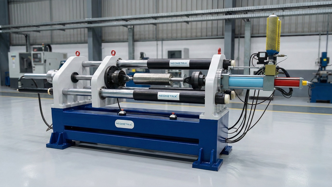
2. Loading structure / test frame. A 200 kN-rated adjustable beam frame with a servo actuator (0-200 kN static, +200 kN dynamic, 250 mm stroke) and a positive hydraulic clamp that stays locked without hydraulic pressure for safe setup.
3. Data acquisition and control console. A rack with operator PC, printer and UPS running LabVIEW-licensed control software with automated report generation, plus a controller with 16 digital inputs, 16 digital outputs and 8 analog inputs (4-20 mA).
Measurement is handled by dual load cells (250 kN and 10 kN) and by an absolute digital linear encoder plus an LVDT for stroke, lost motion and drift displacement.
Safety and Repeatability
– Adjustable mounting and load frame support multiple snubber envelopes and clevis geometries
– Positive hydraulic clamp remains locked even without hydraulic pressure
– Software motion limits and “end-before-stroke-end” protection during drift testing
– Manual provision (hand pumps and manual valves) for contingency movement and measurement when automation is unavailable
Try the Test Run Before You Buy
The product page includes an interactive HMI simulation of the full testing workflow, showing recipes, interlocks and report generation in a browser, in demonstration mode with no data generated. It doubles as a risk-free way to train operators.
Standards and Procurement Context for US, UK and European Buyers
The Neometrix page lists ASME OM, MIL-STD, ISO and IS as reference frameworks. For buyers in the three regions the most relevant context is:
– United States: the ASME OM Code (including the subsection on examination and testing of dynamic restraints, i.e. snubbers) as incorporated into nuclear plant requirements through the NRC rules, plus MIL-STD for defense piping.
– United Kingdom: nuclear safety under the Office for Nuclear Regulation (ONR) and site licence conditions, and DEF STAN for defense programs.
– European Union and wider Europe: national nuclear and pressure-equipment codes and regulators, the Pressure Equipment Directive 2014/68/EU for process piping, and the Machinery Directive 2006/42/EC for the test equipment itself.
– Quality and calibration: ISO 9001 for quality systems and ISO/IEC 17025 for traceable calibration of load and displacement measurement.
Neometrix does not claim certification to these frameworks on its page. The facility’s “qualification testing supported to” list names DEF STAN, STANAG and MIL-SPEC, and results are issued in purchaser-format reports. Send your acceptance criteria and test procedure and Neometrix replies with a clause-by-clause compliance matrix within two working days.
Buyer’s Checklist: 8 Questions for a Snubber Test Bench Supplier
1. Does it test both hydraulic (velocity-locking) and mechanical (acceleration-locking) snubbers?
2. Which tests are automated, and can acceptance criteria be configured to our procedure?
3. What maximum load, stroke and speed does it cover, and does that cover our largest snubber?
4. How are load and displacement measured, and how is the measurement chain calibrated?
5. What reports are produced, and can they follow our purchaser format?
6. What protects the operator and the specimen during setup and during testing?
7. What manual fallback exists if automation is unavailable?
8. What training, simulation and spares are included?
Frequently Asked Questions
What is a snubber, in one sentence?
A snubber is a piping support that allows free thermal movement but locks rigidly in a fraction of a second under sudden loads, protecting piping and connected equipment.
How are hydraulic and mechanical snubbers tested differently?
Hydraulic snubbers lock based on velocity, so the sensitivity parameter is locking velocity. Mechanical snubbers lock based on acceleration, so the sensitivity parameter is locking acceleration. The facility runs the same five-test suite on both families.
Why test in both compression and tension?
Because a snubber must restrain loads in both directions, and defects can be direction-specific. Every test is executed and reported both ways.
Can a snubber be inspected visually instead?
Visual inspection cannot reveal internal drag, lost motion, locking delay or drift. Measured test data is the evidence that a snubber is ready to return to service.
Get in Touch
Send your snubber sizes, loads and test procedure for a tailored response:
– Product page: Dynamic Snubber Shock Arrestor Test Facility
– Email: [email protected]
– Phone: +91-7777-876-876 (India; dial +91 from the USA, UK and Europe)