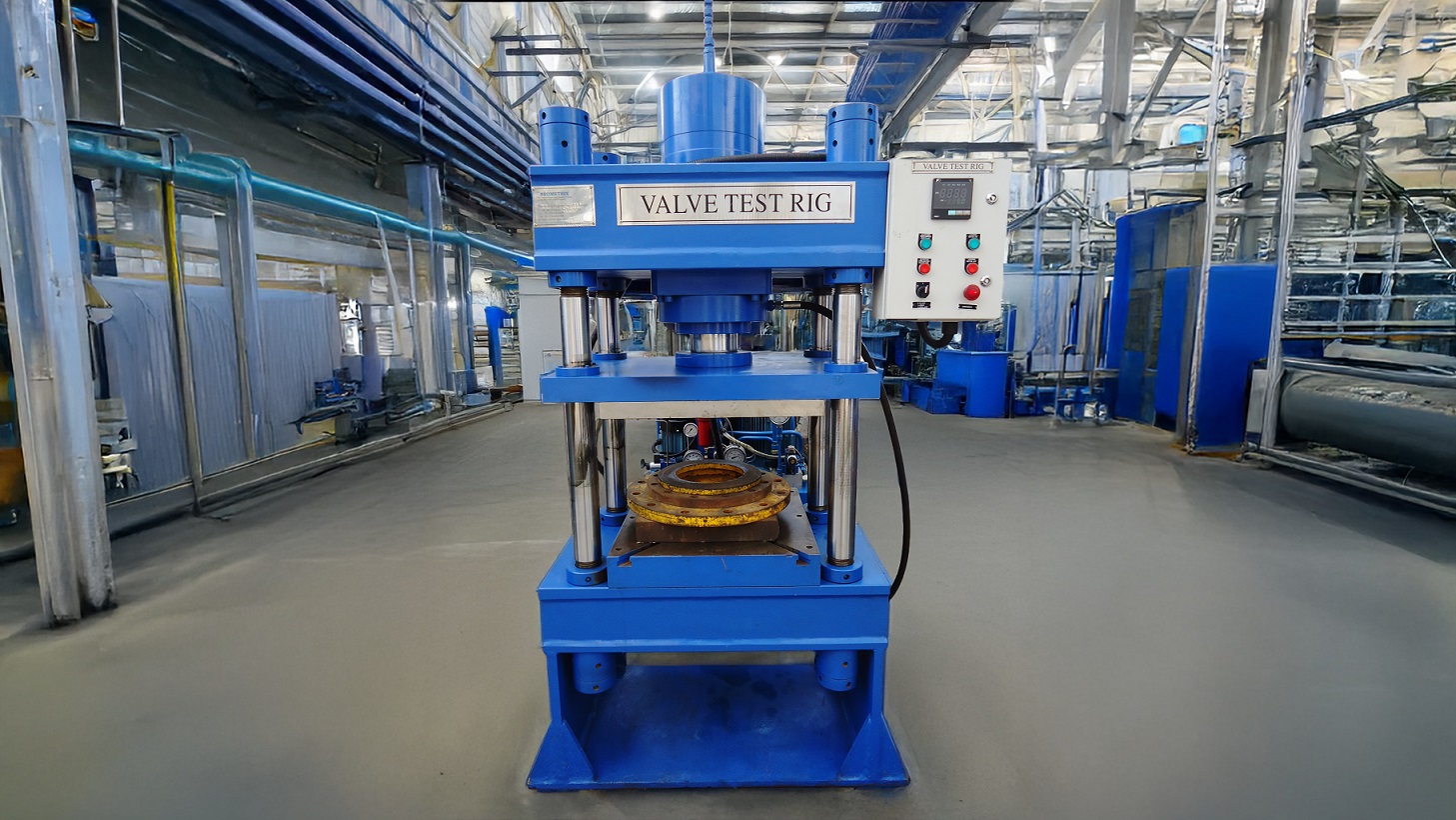

Valve Test Rig: Hydrostatic Pressure Testing With Visual Leak Detection to 135 Bar
A valve can hold its rated pressure on paper and still leak from a seat that never seals cleanly. Neometrix’s Valve Test Rig is a high-tonnage, hydraulic-based system engineered to test butterfly and check valves from 2 to 12 inches (DN50 to DN300), combining hydrostatic pressure testing with a visual leak-detection camera — because a pressure gauge tells you the shell held, not whether the seat actually sealed.
A 65-Ton Press, Clamping Not Crushing
A heavy-duty 65-ton, 4-pillar vertical press with 400 mm stroke clamps the valve between hydraulic working plates using a two-stage relief system: 25 bar for clamping, 135 bar for the actual test loading. Separating those two pressure stages matters — clamping force needs to hold the valve securely without deforming it, while test pressure needs to reach the full 135 bar rating independently.
Two Motors, Two Jobs
A 7.5 HP motor drives the clamping cylinder; a separate 2 HP motor drives the loading circuit. Running clamping and pressure loading off independent motors and circuits means the rig can lock a valve down firmly before pressure ever begins climbing, rather than sharing a single hydraulic source between two functions that need to happen in sequence, not simultaneously.
The Camera Does What the Pressure Gauge Cannot
An industrial camera positioned beneath the valve visually monitors and records the body and seat for any seepage during the test — catching a leak that a pressure reading alone might miss, particularly a slow seat leak on a rubber-seated valve that wouldn’t register as a meaningful pressure drop within a normal test window.
Built to Not Move When It Shouldn’t
Hardened steel clamping pillars are designed for no-flex operation, chrome-plated hydraulic cylinder shafts carry leak-proof seals, and Hydac/Rexroth filtration (20-micron inline, 10-micron return line) keeps the working fluid clean enough that filtration debris never gets mistaken for a genuine leak signature.
Frequently Asked Questions
Why does a valve test rig need a separate visual leak-detection camera if it’s already measuring pressure directly?
Because a pressure gauge and a camera are actually testing for two different kinds of failure. A shell (body) hydrostatic test checks whether the valve body itself holds pressure without rupturing or deforming, and a pressure gauge is well-suited to catching that. But a seat leak — where the valve’s sealing surface lets a small, slow amount of fluid past even though the body itself is sound — can be subtle enough that it doesn’t register as a meaningful pressure drop within a practical test window, especially on larger valves with more system volume to absorb a minor leak. An industrial camera positioned beneath the valve visually monitors the body and seat directly for any seepage, catching exactly this kind of leak that a pressure reading alone might miss — which is why the rig runs both a shell hydrostatic test and a seat leakage test as distinct capabilities rather than relying on pressure measurement alone.
Why does the rig use two separate motors and hydraulic circuits instead of one shared power source for clamping and testing?
Because clamping the valve securely and applying test pressure are two functions that need to happen in a specific sequence, at different pressures, without interfering with each other. The rig uses a 7.5 HP motor for the clamping circuit, regulated to about 25 bar to lock the valve firmly between the working plates without deforming it, and a separate 2 HP motor for the loading circuit, which then ramps pressure up to the full 135 bar test rating. Keeping these on independent motors and pressure circuits means the clamping force stays fixed and reliable throughout the test regardless of what the test pressure is doing, and the system can enforce operational rules — like refusing to apply load without clamping engaged first — through simple sequencing rather than needing to carefully time-share a single hydraulic source between two functions with very different pressure requirements.
Get In Touch
For full specifications, RFQs, or a technical discussion about the Valve Test Rig:
– Product page: Valve Test Rig
– Email: [email protected]
– Phone: +91-7777-876-876