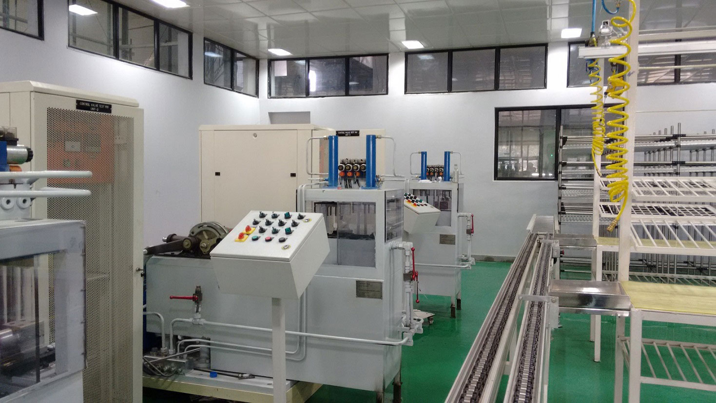

Electro-hydraulic control valves are the interface between electronic control systems and hydraulic actuation — converting electrical signals into controlled hydraulic flow to lift, lower, hold, and position loads in agricultural machinery, construction equipment, industrial hydraulic systems, and vehicle hydraulic circuits. Before any electro-hydraulic control valve is shipped to a customer or installed in a machine, it must be tested to verify that it responds correctly to control signals across its full operating range.
An electro-hydraulic control valve test rig applies hydraulic load conditions and electrical control signals simultaneously, measuring the valve’s actual flow, pressure, and response characteristics against specification — with automated data acquisition generating performance reports for quality documentation.
What an Electro-Hydraulic Control Valve Does
An electro-hydraulic control valve receives an electrical input (typically 4–20mA, 0–10V, or PWM signal) and converts it to a hydraulic output — opening a spool or poppet to allow controlled flow in proportion to the electrical command. The valve controls:
Lift: Applying hydraulic pressure and flow to extend an actuator — raising a load.
Lower: Releasing hydraulic pressure in a controlled manner to retract the actuator — lowering the load at a controlled rate.
Hold: Blocking flow in both directions to hold the actuator at a fixed position — holding the load stationary against gravity and external forces.
In agricultural equipment (tractors, combines), this valve controls the three-point hitch, loader bucket, and implement positioning. In construction equipment (excavators, loaders), it controls boom, arm, and bucket movements. In industrial hydraulics, it controls presses, clamps, and positioning systems.
What the Test Rig Measures
Flow vs command signal: At each electrical input level (0%, 25%, 50%, 75%, 100% of input range), the rig measures hydraulic flow rate through the valve. The flow-vs-signal characteristic must match the valve specification (typically linear or progressive).
Pressure drop vs flow: The valve’s hydraulic resistance at each operating point — determines the pressure available to the actuator.
Hysteresis: The difference in output flow between increasing and decreasing command signal at the same command level. High hysteresis causes poor positioning accuracy in closed-loop control.
Deadband: The command signal range over which the valve produces no output flow. High deadband reduces control sensitivity near zero command.
Response time: How quickly the valve reaches target flow after a step change in command signal. Critical for dynamic control applications.
Internal leakage: Flow past the spool in the hold position with valve commanded to hold. Determines how long a load can be held stationary.
Lift, lower, hold function verification: Confirms that each function (lift, lower, hold) operates correctly with the correct flow direction and pressure response.
International Standards
| Standard | Region | Application |
|---|---|---|
| SAE J1271 | USA/International | Hydraulic control valve test procedure |
| ISO 10100 | International | Hydraulic cylinders acceptance tests (valve-actuator system) |
| ISO 4413 | International | Hydraulic fluid power safety rules |
| ISO 6403 | International | Hydraulic control valves — test methods |
| DIN 24312 | Europe | Hydraulic directional control valves testing |
| ASABE S315 | USA | Agricultural equipment hydraulic systems |
Applications by Industry
Agricultural equipment: Tractor hydraulic control valves (three-point hitch control, remote hydraulic circuits) from major OEMs (John Deere, CNH, AGCO, Mahindra) require end-of-line testing before dispatch. Test rigs are installed at manufacturing plants for 100% production testing.
Construction equipment: Excavator and loader directional control valves from Bosch Rexroth, Parker, and Eaton require qualification testing and production acceptance testing.
Automotive and commercial vehicles: Hydraulic brake valves, power steering valves, and transmission control valves for commercial vehicles are tested for function and leakage.
Industrial machinery: Press control valves, injection moulding machine valves, and machine tool hydraulic control valves require acceptance testing per customer and ISO specifications.
Neometrix Control Valve Test Rig (Automobile)
The Neometrix Control Valve Test Rig is an electro-hydraulic valve tester that simulates lift, lower, and hold load conditions with automated data acquisition and performance report generation.
→ View Full Specifications
→ Request a Quote
FAQ
Q: What is SAE J1271 and what does it specify for hydraulic control valve testing?
A: SAE J1271 is the Society of Automotive Engineers standard for Hydraulic Directional Control Valve Test Procedures. It specifies the test setup, test conditions, measurement requirements, and test sequence for evaluating hydraulic directional control valves. Tests include: pressure drop vs flow, internal leakage, response time, hysteresis, deadband, rated flow at rated pressure drop, and operational function testing. It is the primary reference for automotive and industrial hydraulic valve testing in North America and is widely referenced internationally.
Q: What is valve hysteresis and why does it matter for agricultural equipment?
A: Hysteresis is the difference in output flow when the command signal is increasing versus decreasing at the same command level. High hysteresis means the valve responds differently depending on whether you’re commanding more or less flow — causing inconsistent response in closed-loop position control. In a tractor three-point hitch, high hysteresis means the implement oscillates around the target depth rather than holding position. Hysteresis is specified in valve datasheets and verified on the test rig.
Q: What is internal leakage in a hydraulic control valve and what are acceptable limits?
A: Internal leakage is hydraulic fluid flow past the valve spool in the hold position, when the valve is commanded to block flow. It causes slow drift of the actuator position even when the operator commands hold. In agricultural and construction equipment, internal leakage causes implements to drift down under gravity. Acceptable limits depend on application — typically 5–50 mL/min at rated pressure for agricultural valves. The Neometrix test rig measures internal leakage with a graduated cylinder or flow meter while the valve holds pressure.
Q: What electrical signal types do electro-hydraulic control valves typically use?
A: Common electrical interfaces: 4–20mA current signal (most industrial), 0–10V voltage signal, PWM (pulse width modulation) at 12V or 24V DC (automotive and mobile equipment), and CAN bus (J1939 for agricultural, CANopen for industrial). The test rig must be able to generate the relevant signal type to command the valve under test. The Neometrix Control Valve Test Rig supports multiple signal types for versatility across different valve families.
Neometrix Defence Ltd. manufactures control valve test rigs for automotive, agricultural, and industrial hydraulic valve testing. [email protected] | +91-7777-876-876