Timing and frequency measurement sit at the heart of defence and aerospace electronics verification. Whether validating the output frequency of an avionics oscillator, verifying the timing of MIL-STD-1553 bus transactions, testing the pulse width of a trigger signal, or characterising the jitter of a radar timing chain — these measurements require instrumentation that is precise, repeatable, and traceable.
PC-based counter timer test rigs combine the precision of dedicated frequency counter hardware with the flexibility of software-controlled test sequencing — delivering measurement capability that standalone bench instruments cannot match for complex, multi-channel timing verification tasks.
What a Counter Timer Test Rig Measures
A counter timer test rig can measure any signal parameter that can be expressed in terms of time or frequency:
- Frequency — cycles per second (Hz) of a periodic signal
- Period — time per cycle
- Pulse width — duration of a logic high or low state
- Duty cycle — ratio of pulse width to period
- Rise and fall time — signal transition time between logic levels
- Time interval — elapsed time between two trigger events
- Phase difference — timing offset between two signals
- Totalize — count the number of pulses in a defined window
- Jitter — variation in period or pulse width over multiple cycles
PC-Based Architecture vs Standalone Instruments
Traditional frequency counters are standalone instruments — they measure one parameter at a time, display the result on a front panel, and require manual reading or a GPIB connection for data logging.
PC-based counter timer rigs use PCI, PCIe, or USB counter/timer cards integrated with measurement software (typically LabVIEW) to provide:
- Multiple simultaneous measurement channels
- Automated test sequences with conditional branching
- Software-defined trigger levels and edge detection
- Real-time data logging with timestamps
- Statistical analysis (mean, standard deviation, min/max) over thousands of measurements
- Automated pass/fail against specification limits
- Integration with the broader ATE system (sharing DUT connections, avoiding reconnection)
Applications in Defence and Aerospace
MIL-STD-1553 bus timing verification: MIL-STD-1553 is the primary avionics data bus on military aircraft worldwide. The standard specifies precise timing parameters — word gap, response time, bus idle period — that must be verified during avionics box qualification. Counter timer rigs measure these timing parameters against the specification tolerances.
ARINC 429 avionics bus testing: ARINC 429 is the civil avionics data bus standard. Label transmission rates (12.5 kHz or 100 kHz) and bit timing must be verified per ARINC 429 Part 1 specifications.
Radar and sensor timing: Radar systems use precise timing chains to control pulse repetition frequency (PRF), pulse width, and receiver gate timing. Counter timer rigs verify these parameters during integration testing.
Weapon system fuzing electronics: Fuze electronics use timing circuits to control detonation sequences. Timing verification is a safety-critical test requirement.
Navigation and GPS receiver testing: GPS receivers process timing signals at nanosecond resolution. Counter timer verification is part of navigation system qualification.
International Standards
| Standard | Region | Application |
|---|---|---|
| MIL-STD-1553 | USA/NATO | Avionics data bus timing |
| ARINC 429 | International | Civil avionics bus timing |
| IEC 60068 | International | Environmental testing of electronics |
| IEC 61000-4-8 | International | Timing under EMC conditions |
| RTCA DO-160 | USA/International | Avionics environmental testing |
| IEEE 1588 | International | Precision time protocol |
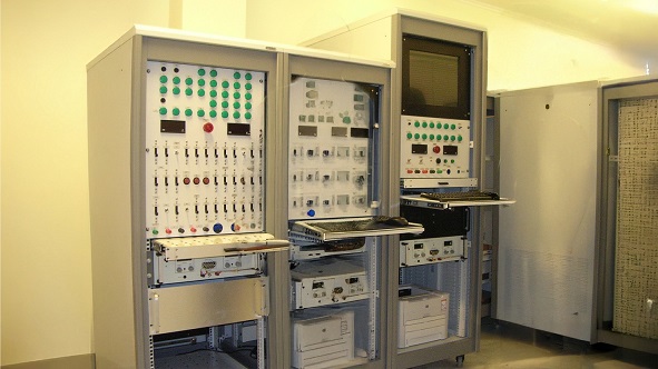
Neometrix PC-Based Counter Timer Test Rig
The Neometrix PC-Based Counter Timer Test Rig is a multi-channel timing and frequency measurement system for defence and aerospace electronics testing. Built on PC/LabVIEW architecture with high-resolution counter hardware, it provides automated test sequences for MIL-STD-1553, ARINC 429, and custom timing verification applications.
→ View Specifications
→ Request a Quote
FAQ
Q: What resolution is achievable with PC-based counter timer systems?
A: Modern PC-based counter timer hardware achieves single-shot time interval resolution of 100 picoseconds or better. For frequency measurement, resolution improves with gate time — a 1-second gate time gives 1 Hz resolution, a 10-second gate gives 0.1 Hz. For defence electronics, frequency measurement uncertainty of better than 1 ppm is typically achievable.
Q: What is MIL-STD-1553 and what timing parameters must be verified?
A: MIL-STD-1553 is the military standard for a serial time-division multiplexed data communication bus used on military aircraft, ships, and vehicles. Key timing parameters include: bit rate (1 Mbps ±1%), word gap (≥2 μs), response time (bus controller to remote terminal: 4–12 μs), and message gap (≥4 μs). Counter timer rigs verify all these parameters during avionics qualification testing.
Q: How is jitter measured in defence electronics?
A: Jitter (variation in timing from cycle to cycle) is measured by capturing the period or pulse width of thousands of consecutive cycles and calculating the standard deviation. PC-based counter timer systems can capture millions of measurements and produce statistical histograms of timing variation — identifying systematic jitter sources and random noise contributions separately.
Neometrix Defence Ltd. builds PC-based counter timer test rigs for defence and aerospace electronics testing. [email protected]