Details
Specifications
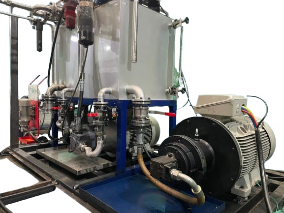
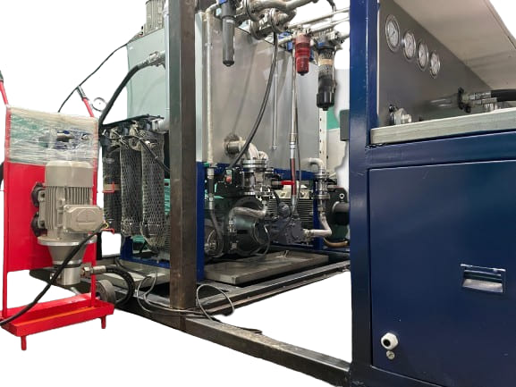
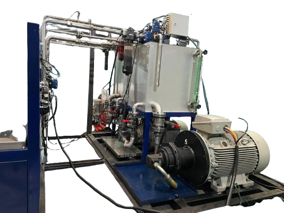
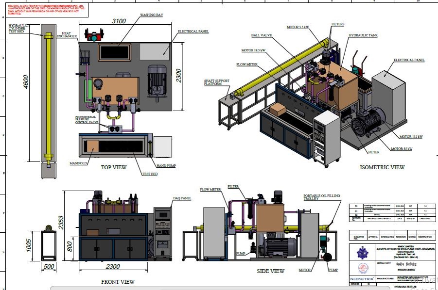
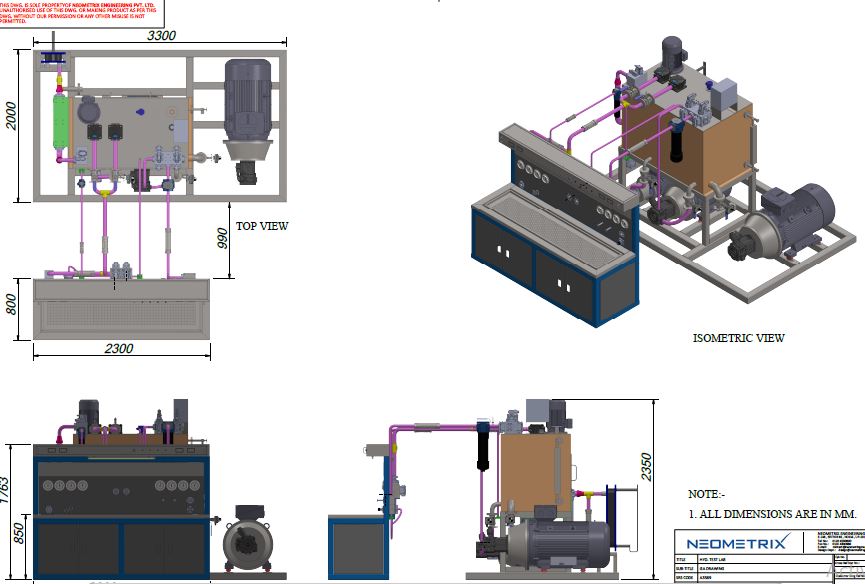
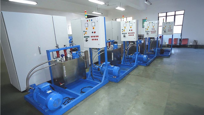
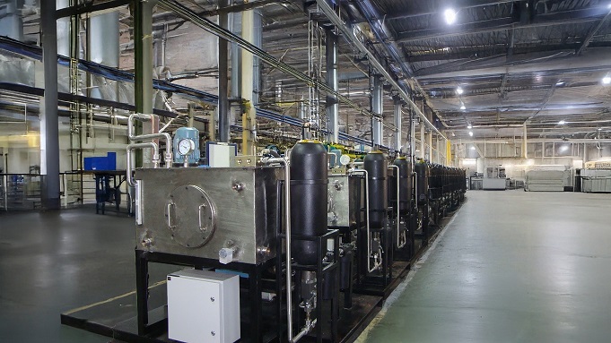
• Hydraulic Oil Tank: Material : SS-304, 1200 Liters Oil Capacity, Dimension - 1500 (L)X900(W)X 1000 (H)
• Drain Valve: 1" Ball Valve- CS ,  End Connection 1'' BSP (F) , Working Temperature 80 degree C, Working Fluid: ISO VG46
• Level Gauge: Length: 700 mm Gauge Glass: Tempered Borosilicate, Wetted Parts: SS304, Max. Temp: 80ºC, Max. Pressure: 10 Bar, working fluid: ISO VG46
• Temperature Gauge: Tank Mounted Temperature Gauge, stem Length 500 mm, Size- 4” (100mm), Range 0-150 degree C, Working Fluid: ISO VG46
• Cooling Line Pump P3: working pressure 10 Bar, flow: 250 LPM @ 1450 RPM
• Cooling Line Motor M3: Flange Mounting ,Three Phase induction Motor, Continuous Duty, Supply 415V AC, 50 HZ, 5.5 kW, 1440 RPM, IE3, 4 Pole
• Safety Relief valve: Set @10 bar, Working Media :Hydraulic Oil, Flow : 280 LPM
• The machine will fully comply with all the features mentioned above. However, some customer-provided specifications will need to be adjusted to ensure optimal performance for this test bench.
•  Motor Requirement: The specified 160 kW motor will not suffice for pump testing. Instead, a 250 kW motor is required to meet the testing requirements.
• Valve Testing: o For valve testing, with a maximum flow of 600 LPM and a pressure of 350 bar, the system will incorporate two major pumps, each capable of delivering 320 LPM at 350 bar, powered by 250 kW motors.
• Material Specifications: o Pipes, tubes, and the hydraulic tank will be constructed from SS304 material for durability and corrosion resistance.
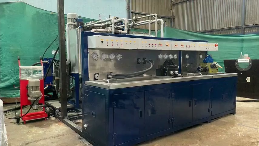
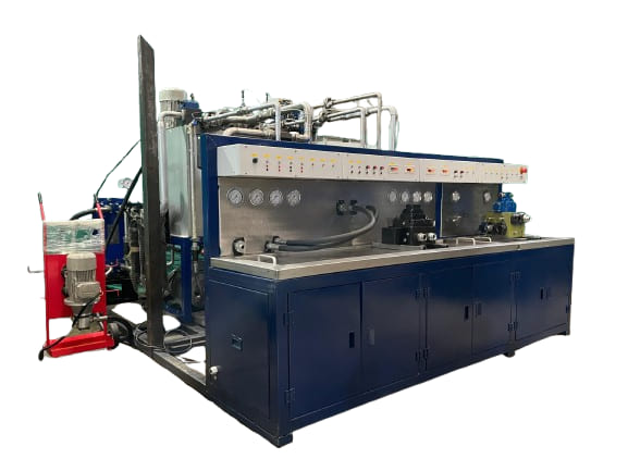
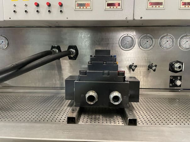
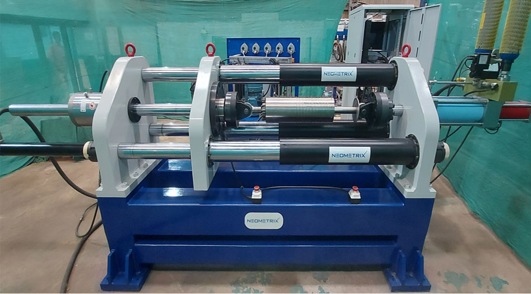
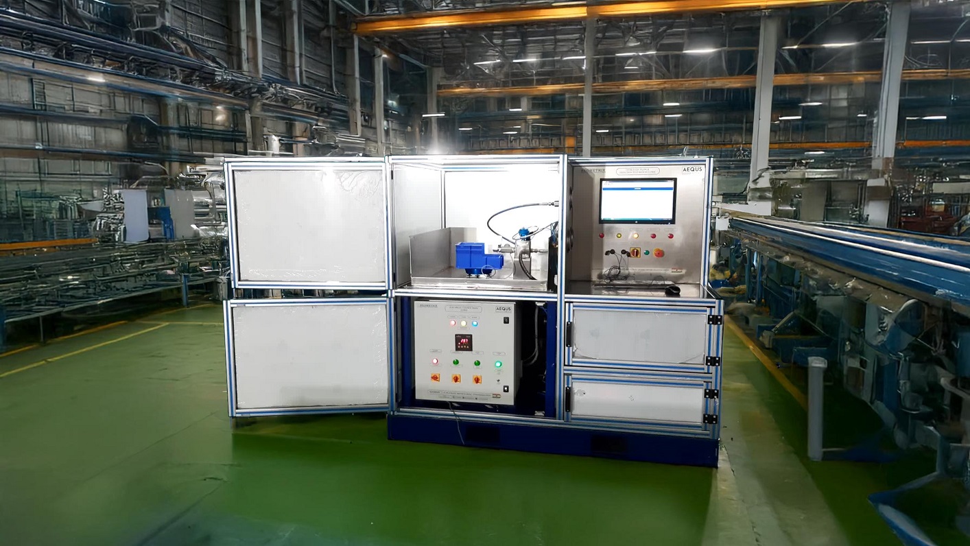
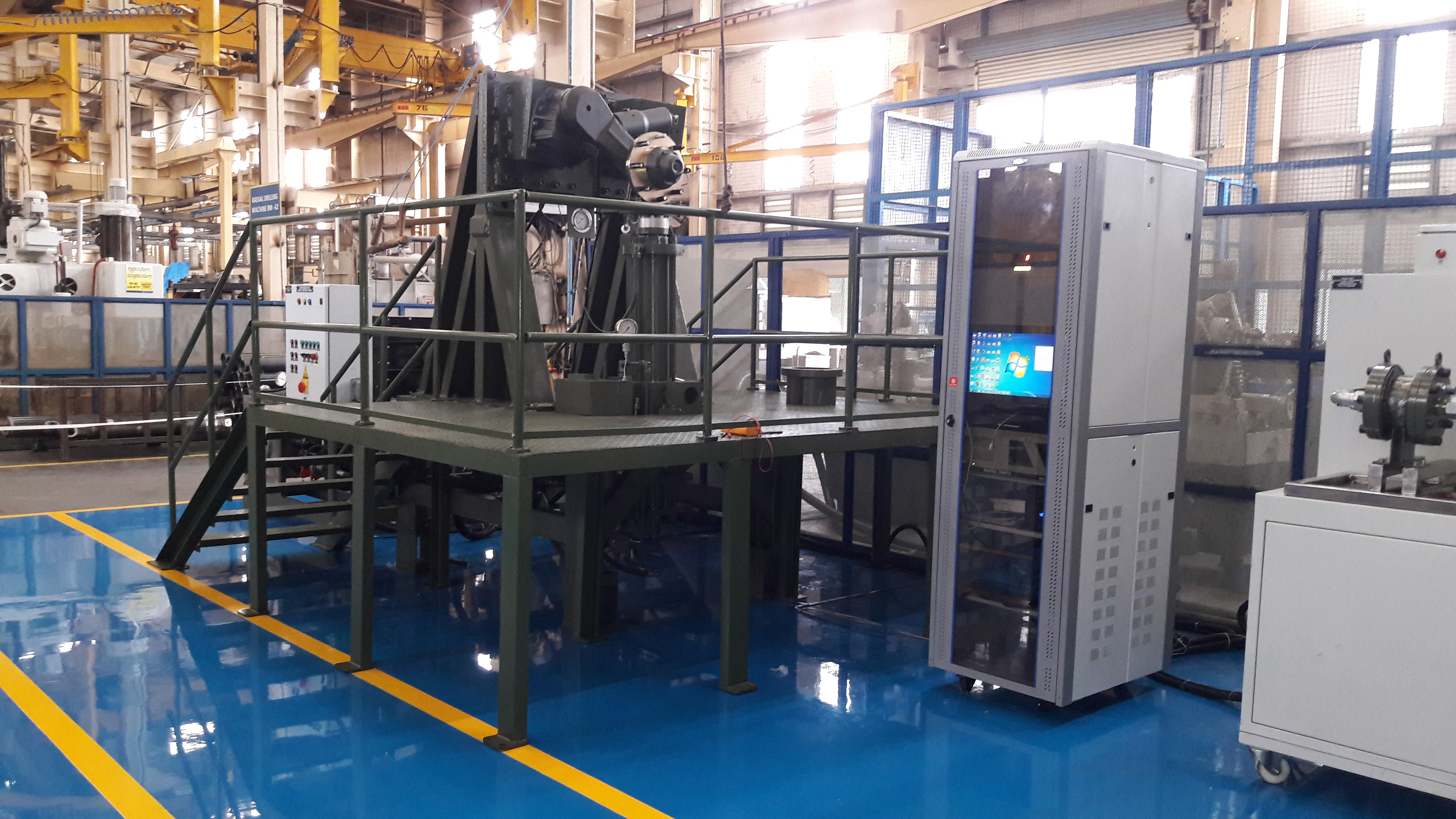
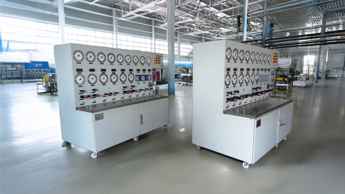
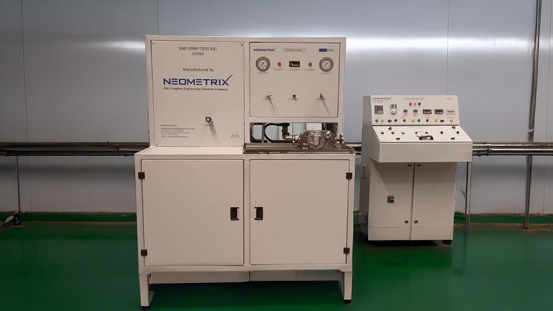
• Test Bench Configuration: The test bench will include three separate beds for testing valves, cylinders, and pump motor assemblies, each with its own control panel. The hydraulic tank will be shared across all test beds. An additional filtration and cooling circuit will be integrated into the hydraulic tank to maintain system efficiency.
• Standard Components: o All components used will be globally recognized and standardized brands, such as Rexroth, Parker, Hydac, and Wika etc.. Ensuring reliability and ease of maintenance.
• Safety Systems: o The machine will include comprehensive safety systems, such as:
Emergency shut-off systems
High-temperature sensors
Overflow protection mechanisms etc..
• Automation: The system will be fully automated, allowing the operator to select the model number of the equipment to be tested via the control panel. Pre-installed programs will guide the operator on fixing the test specimen and automatically execute the test sequence.
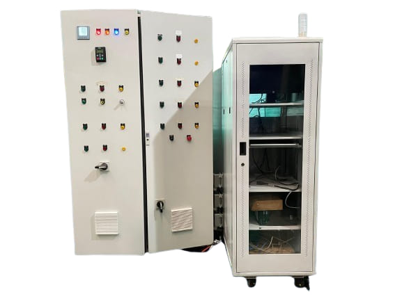
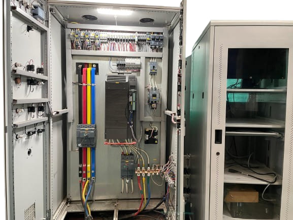
• Electrical and Control Panels: o A common electric panel will serve all test beds, while each bed will have an independent control panel for streamlined operations
• Accessories: o All necessary accessories, such as couplings, sub plates, fixtures, and hoses, etc.. Will be provided with the machine to ensure complete functionality.

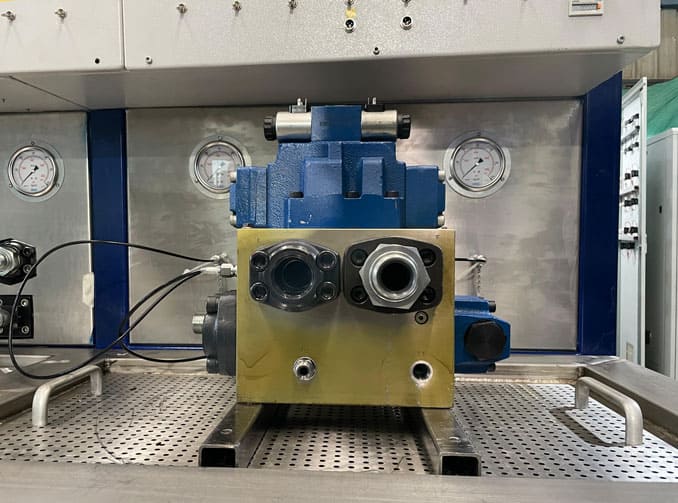
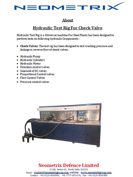
Hydraulic Test Lab has been designed to perform tests on following hydraulic Components:
• Hydraulic Pumps (Fixed/variable Displacement Piston pumps & Single/tandem Gear/Vane pumps)
• Hydraulic Motors (Gear/Vane/Piston Type)
• Pressure control valves.
• Flow control valves.
• Direction control valves.
• Solenoid of DC valves.
• Proportional Control valves.
• Hydraulic Cylinders.
• Check Valves.

i)  Hydraulic Pumps:
The test rig has been designed to test the pump for maximum capacity (flow) of 200 cc/ rev, at 215 bar and internal leakage at rated pressure. Maximum speed of the test motor has been kept as 1450 rpm. It has been designed to test all the High pressure pump (Fixed/ variable Displacement Piston pump), Gear pumps, vane pumps listed in Annexure –IA, at their rated flow @ 1450 RPM with optimum pressure, at rated pressure or maximum test pressure limited to 315bar with Optimum RPM (integrated with VFD starter) and internal leakage at rated pressure with optimum flow.

ii) Hydraulic Motors:
The test rig has been designed to test the Hydraulic motors listed in annexure-IA, at max pressure 315 bar with optimum flow and at max flow 180 LPM @ 150 bar through power control pump motor station, Internal Leakage at rated pressure. Maximum rpm will be 1450.

iii)  Pressure Control Valves:
The test rig has been designed to test the Pressure control valve of sizes NG 6 to NG 30 at rated pressure but maximum pressure limited to 315bars with optimum flow for functional test and internal leakage. Test rig has the capability of testing valves of sizes ranging from NG6 to NG30 using conversion plates

iv) Flow Control Valves:
The test rig has been designed to test the flow control valves of sizes NG 6 to NG 22 at rated pressure but maximum pressure limited to 315 bar with optimum flow, and the functional test will carried out. Test rig has the capability of testing valves of sizes ranging from NG6 to NG22 using conversion plates.

v)  Directional Control Valves:
The DC valve of sizes NG 6 to NG 32 at rated pressure but maximum pressure limited to 315 Bar with optimum flow can be tested for Function and Internal leakage.  Test rig has the capability of testing valves of sizes ranging from NG6 to NG32 using conversion plates.

vi) Solenoid of DC Valves:
An electrical supply line of 24 VDC has been provided for testing the solenoid valves for their function and continuity.


vii)  Proportional control valves:
The valve of sizes NG 6 to NG 32 shall be tested for Flow & pressure at varying voltage / Current input.

viii) Hydraulic Cylinders:
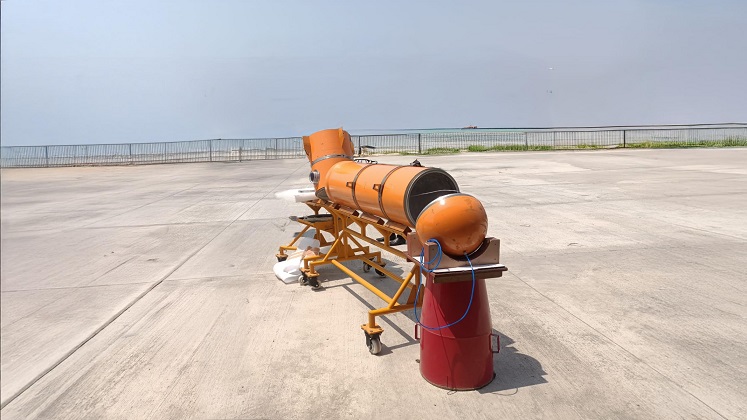
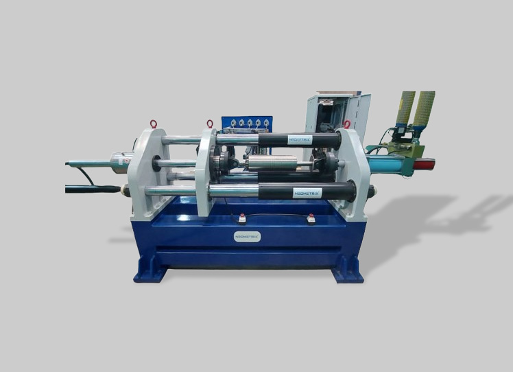
The test rig has been designed to perform leakage test, rated pressure test, cushioning test for hydraulic cylinders listed in annexure-IA at maximum 315 bar pressure and at max flow 180 LPM @ 150 bar through power control pump motor station. Internal leakage test will be carried out for multi positions (Rod end- Cylinder retracted, Cap end – cylinder extended, rod end –mid/intermediate stroke, cap end – mid/intermediate stroke).  Test Rig is capable to test cylinder with a maximum stroke of 4.6 meter.

ix) Check Valves:
The test rig has been designed to test cracking pressure and leakage in reverse flow of check valves.


Automatic Universal Hydraulic testing parameters

Hydraulic Pump testing
The machine capable to perform the pump's performance characteristics by plotting various parameters.(considered maximum pressure 350 bar and maximum flow 600lpm)
• Pressure vs Flow
• Power vs Flow
• Efficiency vs Flow
• Hydrostatic testing

Hydraulic motor testing
The testing which can be performed in this test bench are
• Performance testing (pressure vs flow)
• Load testing (torque, speed)
• Leakage testing
• Starting torque testing

Hydraulic Cylinder testing
• Load testing
• Endurance testing
• Cyclic testing
• Leakage testing

Hydraulic valves testing
The machine is capable to test the different kind of valve i.e. Servo valve, Proportional valve, DC valve , Pressure reducing valve, Pressure relief valve. Major test can be performed
• Hysteresis test
• Flow vs command
• Pressure vs command
• Command vs spool feedback
• Step response test.
• Null position checking
• Null biased test.
• Fail safe condition test


